

Superlok® USA · Tube Fabrication
Bend Radius, Ovality, and Why the Fitting Leaks Afterwards
A bend changes the tube’s shape, its wall and where it wants to sit. All three land on the next joint down the line.
Most leaks blamed on a fitting were built into the tube a foot away. According to the Tube Bender Pocket Guide published by SSP®, a fittings and tooling manufacturer, “when bending tubing, it is important to allow a sufficient length of straight tubing between the shoulder of the tube fitting and the bend.” That sentence is the whole problem in one line. A ferrule seals on a round, straight, uniform piece of tube, and a bend attacks all three of those properties. Tube preparation matters too, and a square, burr-free end is assumed throughout what follows, but cutting and deburring is its own subject and this post is about the bend.
Minimum bend radius comes from the tooling
There is no single minimum bend radius for stainless steel tube. The achievable radius depends on the bending method, the tube outside diameter, the wall thickness and the tooling. A tube fabrication guide from Listertube gives the method-level picture: “standard draw bend radius is 2 x D,” while “minimum roll bending radius is 7 x D.” A bending house that specialises in thin wall work, TEC, uses 3XD as its reference case, which it defines as “a bend radius of three times the tube outside diameter.”
In instrumentation work the radius is usually chosen for you. Hand and bench benders come with a fixed former per tube size, so the practical question is which formers exist for the size you are running. SSP®’s pocket guide lists two radii for 1/4 in. tube, 5/8 in. and 3/4 in., which work out to 2.5 and 3 times the outside diameter. Pick the larger one when the layout allows it, because everything in the next section improves as the radius grows.
What a bend costs you: ovality and wall thinning
Two things happen at once. The cross-section goes out of round, and the outside of the bend stretches and thins. TEC’s technical page defines the first: “ovality measures how much the tube cross-section deforms from round during bending. It is expressed as a percentage: the difference between the maximum and minimum cross-sectional diameter divided by the nominal diameter.” Its worked example has 7% ovality on a 2 in. OD tube leaving the cross-section between 1.86 in. and 2.14 in. at its extremes, and it says plainly that above that level “tube components fail to seal correctly at connection points.”
Codes put a ceiling on the same quantity. A piping engineering reference summarising ASME B31.3 states that under paragraph 332.2.2 the “flattening of bends, measured as the difference between the largest and the smallest outside diameter at any cross section, shall not exceed 8% of the nominal diameter” for internal pressure, with 3% applying at weld ends under external pressure, and that “removal of metal shall not be used to achieve these requirements.” That last clause is worth reading twice, because filing a flat spot to make a gauge fit is exactly the wrong response.
Wall thinning is the quieter problem, since you cannot see it. TEC documents “wall thinning less than 12.5% for 3XD bends” as its internal standard and explains the physics in one line: a tighter radius concentrates the stretch over a shorter arc, so “the wall thins faster,” while a larger radius spreads the same stretch over a longer arc. Thinning on the outside of the bend reduces the wall that carries pressure, which is why design pressure should be checked against the thinnest expected wall rather than the nominal one. Superlok® publishes working pressures on the Superlok® pressure rating pages, and those figures assume the tube meets its stated wall.
Three ways a bend placed too close to a fitting shows up as a leak:
The ferrule seals on an oval
A ferrule is round and is driven along a round taper. Where the ovality of the bend reaches the ferrule seat, contact becomes uneven around the circumference and the seal depends on which way up the tube went in.
The tube never reaches the shoulder
Curvature starting inside the fitting body stops the tube seating squarely on the internal stop shoulder. Makeup then looks normal from outside while the geometry the ferrules were designed around is gone.
Springback loads the joint
A bend that has to be sprung into place puts a permanent side load on the nut. That preload adds to vibration and pressure cycling, and the joint that finally weeps is the one nearest the bend.
Straight length before the fitting
This is the part that gets designed out on a crowded panel and then costs a day in the field. The tube needs enough straight, undisturbed length between the fitting shoulder and the start of the bend for the nut and ferrules to sit on parallel, round material. SSP®’s pocket guide publishes minimum straight lengths by tube size and bend radius for its own benders. Those figures are tied to a specific bender and fitting series, so treat the table below as an indication of magnitude and take your numbers from the bender manual and the Superlok® installation guide for the tube fittings you are installing.
| Tube OD | Bend radius | Radius as multiple of OD | Minimum straight length |
|---|---|---|---|
| 1/4 in. | 5/8 in. | 2.5 x OD | 13/16 in. |
| 3/8 in. | 15/16 in. | 2.5 x OD | 15/16 in. |
| 1/2 in. | 1 1/2 in. | 3 x OD | 1 3/16 in. |
Tube OD, bend radius and straight length are as published by SSP® for its benders. The radius multiples are simple division and can be checked by hand. These are not Superlok® figures and are not a substitute for the bender manual or the installation guide issued for the fitting you are using. Larger sizes are not listed in the source cited.
Support the tube after the bend
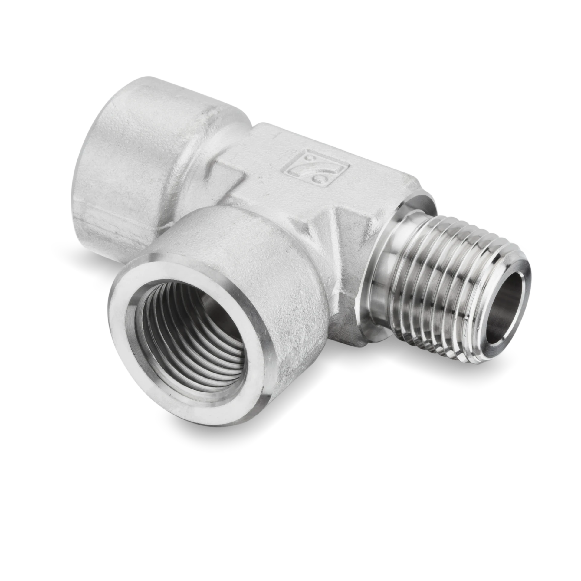
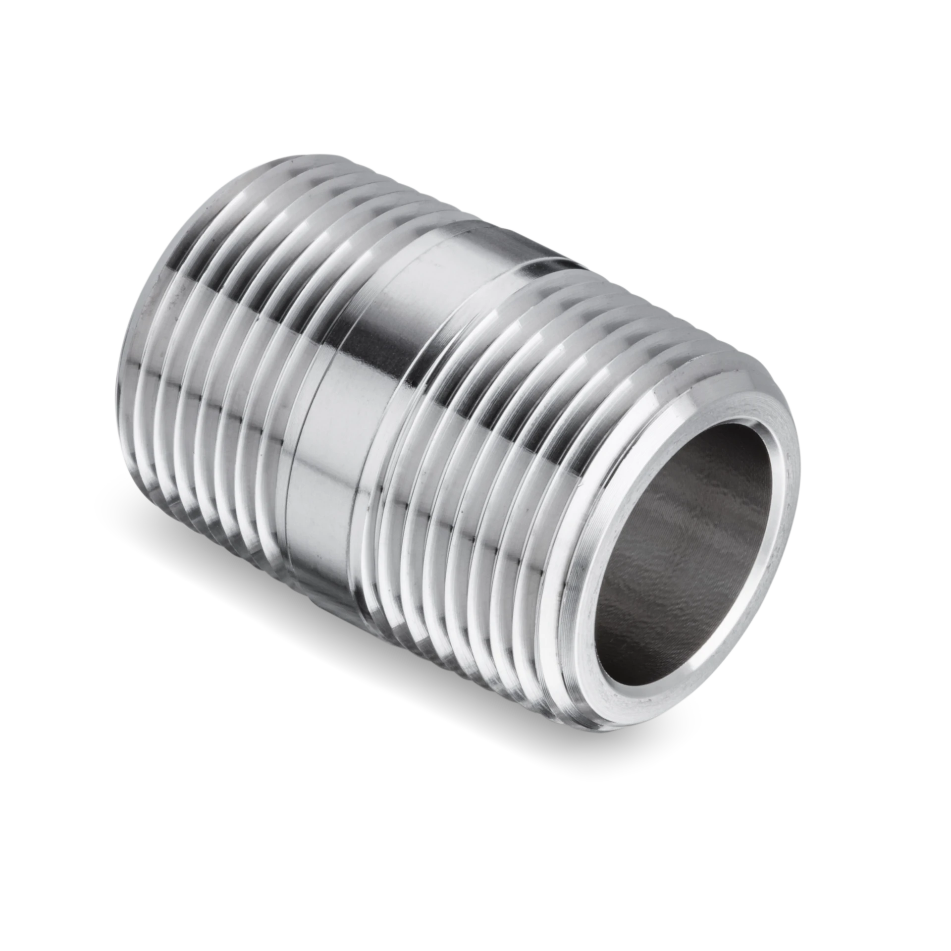
A bend is a spring and a stress concentration in the same place, so it wants to be held. A Swagelok® distributor publication on tube supports states that “all tubes should be clamped on both sides of a bend, as close to the bend radius as possible,” and gives spacing examples of clamps every five feet on half-inch tubing and every seven feet on one-inch tubing. It also warns against letting tubing carry the weight of valves and regulators, which should be mounted separately. Clamping both sides of a bend does two things at once: it keeps springback off the nearest joint, and it stops vibration cycling the bend. On reciprocating plant this is not optional, as our post on oil and gas instrumentation fittings discusses. Superlok® fittings are listed in 316 stainless steel and other corrosion-resistant materials, and are described as having the finest interior surface finish of any tube and pipe fitting on the market, but none of that helps a joint being worked back and forth by an unsupported bend. Clearance dimensions are in the catalog; threaded connections into headers are covered under pipe fittings.
Common questions
Is there one minimum bend radius for stainless tube?
No. It depends on method, diameter, wall and tooling. Published reference points include 2 x D as a standard draw bend radius, 7 x D as a minimum for roll bending, and 3 x OD as a common thin wall reference case.
How do I measure ovality on site?
Measure the largest and smallest outside diameter at the same cross section with a micrometer, subtract, and divide by the nominal diameter. The piping code summary cited sets 8% as the flattening limit for internal pressure service.
Can I file or sand a flattened bend to make it fit?
No. The code summary cited is explicit that removal of metal shall not be used to meet flattening limits. Remake the bend.
What if there is not enough room for the straight length?
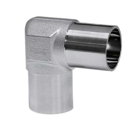
Change the layout rather than the bend. An elbow or a union in the run, or moving the fitting, restores straight tube at the joint. Options are listed in the fittings catalog.
Do thinner walls bend better?
They bend more easily and go out of round more easily. Thin wall on a tight radius is the combination most likely to produce both ovality and thinning, so give it the larger radius and check the finished section.
Laying out a panel and short on straight run?
Send the tube size, wall and bend radius and we will quote fittings that fit the layout you have.
Superlok North America
Round tube, straight run, then the wrench.
Sources
- SSP, “Tube Bender Pocket Guide,” SSPTBPG-24A, manufacturer publication. Supports the requirement for sufficient straight tubing between the fitting shoulder and the bend, the bend radii listed per tube size, and the minimum straight lengths for 1/4, 3/8 and 1/2 in. tube. myssp.com
- TEC, “Thin-Wall Tube Bending Ovality Control for OEMs,” tube bending fabricator publication. Supports the definition and formula for ovality, the 7% worked example on 2 in. OD tube, the statement about failing to seal at connection points, the 12.5% wall thinning standard on 3XD bends, and the effect of radius on thinning. tectubebending.com
- Piping World, “Pipe Fabrication Tolerances,” piping engineering reference summarising ASME B31.3. Supports the 8% flattening limit for internal pressure, the 3% figure at weld ends for external pressure, the paragraph 332.2.2 citation, and the prohibition on removing metal to meet the tolerance. piping-world.com
- Listertube Tube Engineering Services, “Tube Bending Design Guide,” tube fabricator publication. Supports 2 x D as the standard draw bend radius and 7 x D as the minimum roll bending radius. listertube.com
- Swagelok® Northern California, “Give Your Tubing All The Support It Deserves,” distributor publication. Supports clamping on both sides of a bend as close to the radius as possible, the five foot and seven foot clamp spacing examples, and the warning against using tubing to support other components. northerncal.swagelok.com
Technical note: the bend radii, straight lengths and clamp spacings quoted here come from manufacturer, distributor and fabricator publications and apply to the tooling, tube and fitting series each source describes. The 8% and 3% flattening figures are quoted from a piping engineering reference summarising ASME B31.3 paragraph 332.2.2, not from the code text itself, so confirm them against the governing edition of the code for your project. The 12.5% thinning figure is one bending house’s internal standard, not a code limit, and the 7% ovality example is an illustration rather than a universal acceptance criterion. The radius multiples in the table are arithmetic from the published dimensions. None of these sources tested a Superlok® product, and none of them establishes a leak rate or a service life. Superlok® material grade, pressure rating and configuration are confirmed per order.
Superlok® is a registered trademark of its owner. Swagelok® is a registered trademark of Swagelok® Company. SSP®, TEC and Listertube are marks of their respective owners. All other marks are the property of their respective owners. Superlok North America is not affiliated with, endorsed by, or sponsored by any other manufacturer named here. Cross-references are made by form, fit, and function only.