Superlok Installation Guide
Superlok fittings are precision-engineered components designed for reliable and leak-free connections in various fluid and gas systems. Proper installation ensures optimal performance and safety.
Superlok Tube Fittings Installation
Installing Superlok tube fittings requires precision and attention to detail to ensure leak-free and secure connections. Superlok tube fittings are widely used in various industries due to their reliability and ease of installation.
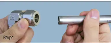
Step 1
Insert the tubing into the loosely assembled SUPERLOK Tube Fitting. At this point, make sure that the tubing is in contact with the shoulder of the fitting and then finger-tighten the nut.
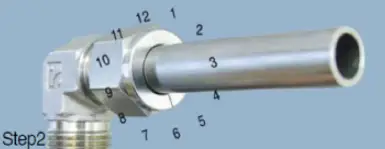
Step 2
Before tightening the SUPERLOK nut, mark the starting point at the 6 o'clock position.
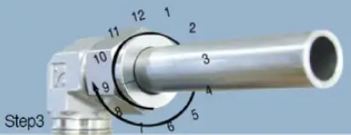
Step 3
Hold the fitting body safely with a backup wrench and tighten the nut 1-1/4 turn. (Marking the starting point at the 6 o'clock position will help reference the 1-1/4 revolution). After 1-1/4 revolution, when the starting point is now at 9 o'clock position, you can easily confirm and see that SUPERLOK Tube Fitting is installed accurately. After 1-1/4 revolution of the SUPERLOK nut past finger-tightening, make sure fitting is sufficiently tightened using by the Gap Inspection Gage.
Gaugeability
On initial installation, the Superlok Inspection Gauge assures the installer or inspector that a fitting has been sufficiently tightened. Position the Superlok Inspection Gauge next to the gap between the nut and the body.
- If the gauge will not enter the gap, the fitting is sufficiently tightened.
- If the gauge will enter the gap, additional tightening is required.
If the gauge will not enter the gap, the fitting is sufficiently tightened.
If the gauge will enter the gap, additional tightening is required.
Re-Tightening Instructions
Step 1
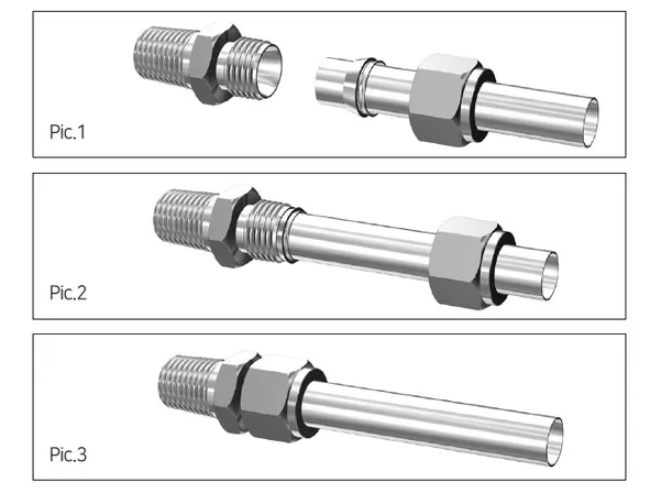
Pic. 1 shows the fitting in the disconnected position. Insert the tubing with the pre-swaged ferrules into the fitting body making sure the front ferrule is firmly seated as shown in Pic. 2.
Step 2
Finger-tighten the nut and then with a wrench turn the nut to the original 9 o’clock position. At this point a slight change of resistance will be felt. Tighten the nut slightly more as the change in resistance is felt and the installation is complete as shown in Pic. 3 by tightening slightly more.
Installation for high pressure or severe service systems
Since tubing has different O.D. tolerances, it is important to have a common starting point to take out in dimensional variations. This is done by tightening the fitting slightly until the tubing can not freely rotate in the fitting as it can in the finger-tight position. At this point tighten the nut 1-1/4 turns. Additional Safety Considerations on Installations for High Pressure Systems.
Make sure the proper tubing wall thickness is selected in accordance with pressure ratings.
Tubing should have a hardness of HRB 80 or less.
Do not assemble or disassemble fittings when the system is pressurized.
Always use an inspection gauge to ensure the fitting is properly installed and tightened.
Gas System Application
Superlok Tube Fittings are appropriate for Gas Systems, but the implementation of certain standards mentioned below should be adhered to just as in other systems.
Tubing hardness must be less than that of the ferrules.
Tubing should be free of surface imperfections, defects and round in shape.
Refer to Table 2 on page 14 for selection of the appropriate wall thickness. (Only shaded areas should be selected for Gas Systems)
Tubing ends must be cut squarely and perpendicular to the center-line of the tubing. After the tubing is cut it must be deburred on both the inside and outside with a High quality fully sharpened deburring tool.
Follow the SUPERLOK Installation Instructions from pages 10 to 11 in the catalog.
Do not attempt to bend the tubing after a fitting has been Installed in a fixed position.
Tubing Systems should be installed to allow for adequate expansion and contraction as well as ease of maintenance.
Tube Adapters
Installation Instructions
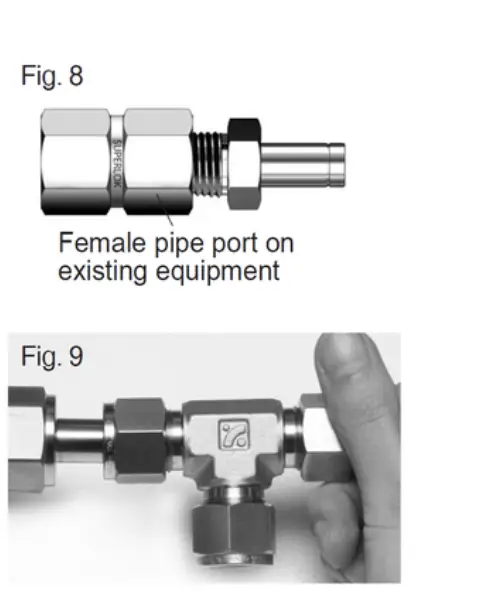
- Install the end opposite the tube adapter end (fig. 8)
- Insert the tube adapter into the SUPERLOK tube fitting. Make sure that the tube adapter rests firmly on the shoulder of the tube fitting body and that the nut is finger-tight.(fig. 9)
- Scribe the nut at the 6 o’clock position.
- While holding fitting body steady, tighten the nut 1 1/4 Female pipe port on existing equipment turns (see note) to the 9 o’clock position.
Note: For 1/16, 1/8, and 3/16 in. : 2, 3, and 4mm tube fittings, tighten the nut 3/4 turn to the 3 o’clock position.
Hardness Limitation
High quality stainless steel tubing that is fully annealed; Seamless or Welded per ASTM A269, A213 or equivalent should be used with Superlok Tube fittings. The tubing must be a maximum hardness of HRB 90 or less on the Rockwell Scale, however HRB 80 is more suitable for bending and offers a greater difference in hardness to the ferrules. This difference in hardness offers more ease in assembly and better interaction between the ferrules and the tubing.

Compatibility
Superlok Tube fittings are designed and manufactured to be interchangeable with other Tube Fittings manufactured by other industry leading manufacturers. When required compatibility testing can be performed by an independant third party and the reports can be provided. Please consult BMT(Superlok) sales representative for compatibility
Superlok Tube Fitting To AN Adapter
Tighten the AN nut by hand.
Rotate the AN nut with a wrench until a significant increase in resistance is encountered.
Tighten slightly with a wrench.
Port Connectors
Installation Instructions- Machined Ferrule End
- Remove the nut and ferrules from one SUPERLOK tube fitting end.
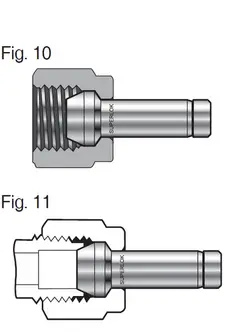
- Place the nut over the machined ferrule end of the port connector (fig. 10).
- Turn the nut onto the fitting so that it is finger-tight (fig. 11).
- Scribe the nut at the 6 o’clock position.
- While holding fitting body steady, tighten the nut 1/4 turn (see note) to the 9 o’clock position.
Note: For 1/16, 1/8, and 3/16 in. : 2, 3, and 4mm tube fittings, tighten the nut 1/8 turn.
Industry Leaders Using Superlok
