

SUPERLOK® NORTH AMERICA · VALVES
Excess Flow Valve Installation: Orientation and Placement
Where the valve goes, which way it faces, how to prove it works before the line is released, and how to bring it back after a trip.
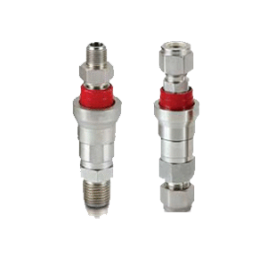
A valve fitted the wrong way protects nothing, and the fault is rarely visible afterward. According to the Fisher® F Series instruction manual (form MCK-1060, May 2009), a manufacturer publication for LP-gas and ammonia valves, a valve fitted where piping restricts its inlet may be prevented from closing, and flow must follow the arrow stamped on the body. Correct excess flow valve installation therefore comes down to four decisions: position in the line, direction, mounting angle and proof by test. The same discipline applies to the excess flow valves from Superlok®. Sibling guides cover gas service, propane, the mechanism and sizing.
Excess Flow Valve Installation: Where It Goes Relative to the Source
Put the valve as close to the supply as practical, so that it covers the longest possible length of downstream tubing. The federal rule for utility service lines, 49 CFR 192.381, says to place one as near as practical to the fitting where the service line meets its gas supply source. In a plant the equivalent is the process tap, the manifold outlet or the regulator, on the supply side of whatever you are protecting.
Three practical points follow. Fit it downstream of the root or isolation valve so the branch can still be shut off, as set out in root valve vs isolation valve. Leave the valve reachable; Dormont’s notice for its appliance valve calls for an easily accessible, well ventilated location, with the manual shutoff in the same room and within 6 feet, and says never to mount it directly on the appliance or its regulator. And think about what the valve must not interfere with: 49 CFR 192.381 advises against fitting one where it would block necessary operation and maintenance, such as blowing liquids out of a line, or where known contaminants could make it malfunction.
Three installation mistakes recur in the manufacturer documents cited here.
Reversed
Swagelok® sends a flow direction verification card with its valve and tells the installer to check the arrow. Fisher® lists wrong direction as a cause of chattering and failure to close.
Choked inlet
Hose or piping that restricts the inlet can stop the valve closing. Piping on both sides must pass more than the valve’s rating, or protection is lost.
Never proved
A valve that was not tested may sit open on a break, or trip on routine flow. Both are found by a deliberate test.
Flow Direction and Mounting Angle
Direction is simple: the body is marked, and the arrow must point downstream. Orientation is less simple, because gravity acts on the moving parts. Some designs are rated for several positions and others for one. Dormont lists its model EFV40-V10 as multi-poise (horizontal, vertical up or vertical down), then gives a different rated trip flow for each: 310, 330 and 295 kBTU/hr respectively, measured on natural gas at a stated pressure drop. That is one appliance valve, and the figures are not a guide for other products. The Fisher® table notes that its rated closing flow applies to the horizontal position. Our own check valve guide, check valve orientation, makes the same point for another spring-loaded part.
The Superlok® product page does not state a mounting position. Use the orientation in the valve documentation supplied with your order, and mount at that angle, since ratings can differ by position.
Before You Pressurise
- Work the poppet by hand if the design allows it. Fisher® says to do this to confirm shipping did not damage it and dirt is not blocking it.
- Clear the run of pipe scale and weld slag, which the same manual names as a reason a valve stays open.
- Seal tapered threads with a compound suited to the fluid; our guide to NPT thread sealant sets out the choices. Swagelok® gives separate assembly steps for its tube end connections, and our installation guide covers Superlok® make-up.
- Open the supply slowly. Dormont warns that opening it too quickly can trip its valve.
Testing, Then Resetting, in Practice
Test twice: once for what must not happen, once for what must. The Swagelok® service instructions (MS-CRD-0064, Rev. D, June 2026) require the valve to stay open through ordinary flow and the heaviest expected surge, and to trip when the line is vented to simulate a break. They add a reset test and a leak check to atmosphere. Fisher® describes a different route: pressurise, then open a shutoff at the farthest protected point quickly, and a sudden drop in flow shows it closed. It warns that testing with flammable gas is hazardous and calls for trained people, a safe place and local permission.
A 1973 report in the Nuclear Regulatory Commission archive repeated its trip check once to prove the valve moved freely and reset. Do the same: one trip proves it closes, a second shows it recovers.
Resetting takes patience. According to Fisher®, shut a valve upstream or downstream and wait; when pressure equalizes the valve clicks open, and flow resumes once the shutoff is reopened. Dormont puts its own valve’s recovery at about 60 seconds. If the valve does not recover, the cause is usually a downstream path still bleeding pressure away, so find that first. Fisher® calls its valves non-repairable and says to replace one that does not function, and Swagelok® says to depressurise and purge before servicing an installed valve.
Finally, put the check on a schedule. The Fisher® manual suggests verifying closure annually or on a regular basis. Our view is that any trip event deserves a record as well, since a valve that tripped once may be telling you something about the line.
We list stainless steel valves, with 316 stainless steel as a corrosion-resistant choice for wetted parts. Grade and rating are confirmed per order; see the tube fittings range for the connections that sit around the valve.
Questions From the Installer
Can it go anywhere on the line?
Near the source, downstream of the isolation valve, reachable, and with unrestricted piping at its inlet.
What if I cannot tell which way it faces?
Read the arrow on the body. If it is hidden, check the data sheet before the valve goes into service.
Is a tripped valve tight enough to leave unattended?
No. It passes a small bleed flow by design, so isolate the line with a manual valve for repairs.
Does the Superlok® page set a test procedure?
No. Use the methods published by manufacturers as a model and follow the documentation shipped with your valve.
Careful fitting counts for little without clean passages, so we finish on how we describe ours.
SUPERLOK® NORTH AMERICA
Fittings machined to the finest interior surface finish of any tube and pipe fitting on the market
Sources
- Emerson (Fisher®), “F Series Excess Flow Valves for LP-Gas and Anhydrous Ammonia Instruction Manual,” form MCK-1060, May 2009 (manufacturer publication): arrow direction, inlet restriction, piping capacity, pre-installation check, test, reset, annual check, non-repairable, horizontal rating. emerson.com
- Swagelok®, “XS Series Excess Flow Valve Service Instructions,” MS-CRD-0064 Rev. D, June 2026 (manufacturer publication): flow direction check, trip and reset tests, leak check, depressurise before service. swagelok.com
- Dormont Manufacturing, a Watts company, “IOM-D-Foodservice EFV 2547” installation and operation manual, 2025 (manufacturer publication): location, 6 foot shutoff distance, multi-poise ratings, slow opening, 60 second reset. watts.com
- U.S. Government, “49 CFR 192.381 Service lines: Excess flow valve performance standards,” as published by Cornell Law School’s Legal Information Institute: location near the supply fitting, advice against fitting where it interferes with maintenance or contaminants are known. law.cornell.edu
- Northern States Power Company, “Report on Instrument Line Excess Flow Check Valve Test Program,” July 27, 1973, hosted by the U.S. Nuclear Regulatory Commission: trip check repeated once to confirm free movement and reset. nrc.gov
- Superlok North America, “Excess Flow Valves” product page (manufacturer publication): no mounting position or test procedure is given. superloknorthamerica.com
Technical note: The sources establish what three valve manufacturers, a federal utility rule and a 1973 test report say about placing, orienting, testing and resetting flow-tripped valves of their own designs. The kBTU/hr figures belong to one appliance valve. They do not establish mounting positions, test procedures, trip flows or approvals for any Superlok® product. Material grade and pressure rating are confirmed per order.
Trademark disclaimer: Superlok® is a registered mark of its owner. Fisher® and Swagelok® are registered marks of their respective owners. Emerson, Dormont, Watts and Cornell Law School are named only to identify sources. Cross-references are made by form, fit, and function only.